GNUnilink.Schematics History
Hide minor edits - Show changes to markup
You dont need the power control part of the schaer programmer (the D3 pin)
You dont need the power control part of the schaer programmer (the D3 pin)
Schaer programmer troubleshooting
- First configure schaer programmer in icprog
- don't forget the nt driver in wondows xp
- Your parallel port must be mapped at address 0x3F8 in your bios
- do in icprog hardware check, you can toggle the programming signals. don't forget to apply power to your gnunilink
- when toggling data in, data out should also toggle
- if not, check that parallel port pin 2 voltage changes when you toggle data in
- if yes, your icprog parallel port setting is working. Check 7407 power and check voltage on 7407's pin 2. it should toggle. Then check pins 13 and 12, they should also toggle.
- if not, check your icprog settings and your parallel port settings.
IMPORTANT:
- The schaer programmer works with the parallel port, not the serial (rs232) port!
- Don't forget to connect the parallel port ground (one pin from pin 18 to 25) to the gnunilink ground.
This diagram was originally created by Devro using TinyCad.
The PNP and NPN transistors can be any small signal transistor. The 2N3055 can replaced by any power transistor. This transistor will dissipate 3W to 5W, which is quite a lot. The 2N3055 has a TO3? case which might not need a heatsink, although it is very hot (about 70-80 degrees celcius). If you choose any other case like TO220?, you must use a heatsink.
The PNP and NPN transistors can be any small signal transistor. The 2N3055 can replaced by any power transistor. This transistor will dissipate 3W to 5W, which is quite a lot. The 2N3055 has a TO3 case which might not need a heatsink, although it is very hot (about 70-80 degrees celcius). If you choose any other case like TO220, you must use a heatsink.


You dont need the power control part of the schaer programmer (the D3 pin)
You dont need the power control part of the schaer programmer (the D3 pin)
You dont need the power control part of the schaer programmer (the D3 pin)
You dont need the power control part of the schaer programmer (the D3 pin)
                                                       5v

                                                       |14
                           5V-[10K]--+       +---------+--------+
                  1|\  2             |     13|                  |
  D0 (2)-----------+  >--------------+-------+ RB7/Data         |
                   |/                |       |                  |
      +5V-[10k]-+                    |       |                  |
                | 12 /|13            |       |    PIC 16C84     |
Busy (11)-------+--<  +--------------+       |     18 pin       |
                     \|                      |    ZIF Socket    |
                            5V-[10k]--+      |                  |
                  3|\  4              |    12|                  |
   D1 (3)----------+  >---------------+------+ RB6/Clock        |
                   |/                        |                  |
                           12V-[10K]--+      |                  |
                  5|\  6              |      |                  |
   D2 (4)----------+  >---------------+-o   4|                  |
                   |/                   o----+ -MCLR/Vpp        |
                  (7407)            5v--o    +---------+--------+
                                                       |5

                                                       GND
              5V
              |14
           +--+--+
           | 7407|
           +--+--+
              |7
             GND
The schaer gif image was kindly provided by alexei. The old text schematic can be found here
In situ Schaer programmer
If you don't have a programmer, you can make one on the same board, so you don't have to unmount your pic device each time you want to program the pic. You can then program the pic directly in the gnunilink.
The original schaer programmer schematic is the base. It is compatible with icprog and uses the parallel port.
For the power take the 12v from the unilink connector and the 5v from the regulator (the same from your pic)
                                                       5v

                                                       |14
                           5V-[10K]--+       +---------+--------+
                  1|\  2             |     13|                  |
  D0 (2)-----------+  >--------------+-------+ RB7/Data         |
                   |/                |       |                  |
      +5V-[10k]-+                    |       |                  |
                | 12 /|13            |       |    PIC 16C84     |
Busy (11)-------+--<  +--------------+       |     18 pin       |
                     \|                      |    ZIF Socket    |
                            5V-[10k]--+      |                  |
                  3|\  4              |    12|                  |
   D1 (3)----------+  >---------------+------+ RB6/Clock        |
                   |/                        |                  |
                           12V-[10K]--+      |                  |
                  5|\  6              |      |                  |
   D2 (4)----------+  >---------------+-o   4|                  |
                   |/                   o----+ -MCLR/Vpp        |
                  (7407)            5v--o    +---------+--------+
                                                       |5

                                                       GND
              5V
              |14
           +--+--+
           | 7407|
           +--+--+
              |7
             GND
If you have a 7407, do like the original. I did not have 7407 so I used NPN transistors. The simplification is that you only need 2 open collector inverter that you can implement with a npn transistor: the one from D0 to RB7 and the one from D2 to MCLR
if you do the simplification dont forget to invert the data out and clock in icprog.
For MCLR, I used a 3 way jumper selecting the programming or the functionnal mode. There surely is an automatic way but I did not test it.
You dont need the power control part of the schaer programmer (the D3 pin)
- the reset connection on the schematic on pin 2 is actually unused and useless.
The PNP and NPN transistors can be any small signal transistor. The 2N3055 can replaced by any power transistor. This transistor will dissipate 3W to 5W, which is quite a lot. The 2N3055 has a TO3? case which might not need a heatsink, although it is very hot (about 70-80 degrees celcius). If you choose any other case like TO220?, you must use a heatsink.
The schematics theorically outputs about 8,2V. The voltage does lower even more when current is drawn (about 0.5V for 0.5A). If you want more voltage, you can add another 1n4148 in serial of the other one.
Attach:

Attach:
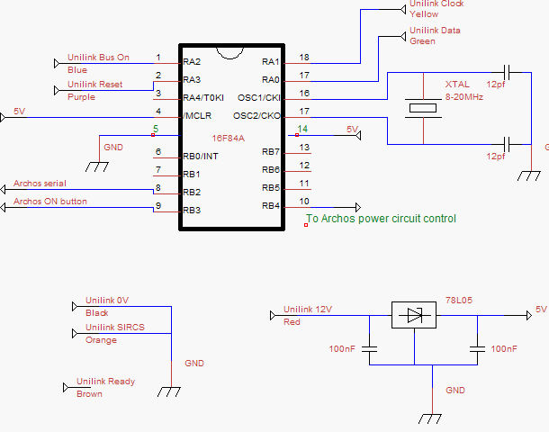
- The 'auto power on' feature isn't complete, since Sophana is the only one who knows how to implement it.
- The 'auto power on' pin is directly connected to the archos power on button wire through a connector of your choice. See the Howto.
This diagram was originally created by Devro using TinyCad.
- The 10K pulldown on RB4 was removed. It was for CD/MD mode selection?
This diagram was originally created by Devro using TinyCad.
Power control section
This part does generate the archos power. It is controlled by the pic. It should not be needed for flashed rockbox, because pressing power on during the battery charge screen should power on the archos. This is not the case for not flashed archos.
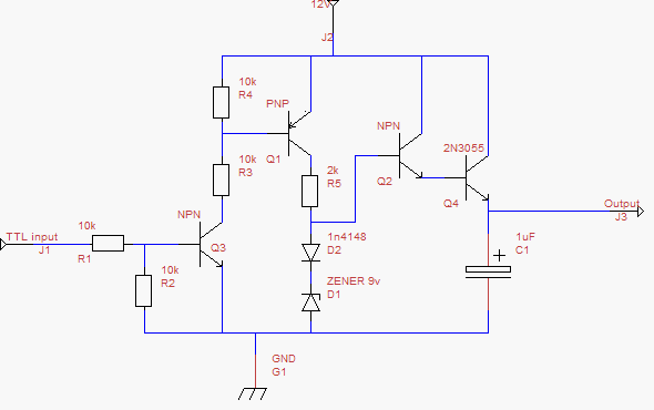
This diagram was created by Devro using TinyCad. We should probably put this image and its source file somewhere more accessible.
This diagram was originally created by Devro using TinyCad.
GNUnilink schematic
GNUnilink schematic
- TODO: the in-circuit Schaer programming circuit should be here.
This diagram was created using TinyCad. We should probably put this into the Subversion repository, so that others can contribute.
This diagram was created by Devro using TinyCad. We should probably put this image and its source file somewhere more accessible.
GNUnilink schematic
This is a recommended circuit for use with the Archos. Please note that there are a few loose ends, since it is currently a work in progress.
This circuit differs from the original GNUnilink such that:
- The 'auto power on' feature isn't complete, since Sophana is the only one who knows how to implement it.
- I have removed the Unilink Reset circuitry, since it was causing severe problems with my HU. Sophana reported that he didn't think it was needed either.
- The 10K pulldown on RB4? was removed. What was it for anyway?
This diagram was created using TinyCad. We should probably put this into the Subversion repository, so that others can contribute.